Unreal Shader Learning
Installation and Basic Concepts
Zhihu: “Shader from Zero to Hero” — you can install ShaderToy in VS to experiment with GLSL
👆 This written tutorial is also really solid.
Unreal 5.0 — Adding Custom Shader Code Inside a Material — In UE you need to configure the shader file path.
The typical 3D pipeline looks like this: “Concept artist draws the scene (translating the 3D world onto paper) -> Modeler builds scene geometry based on the concept art (outputting 3D models) -> Programmer renders it (importing the 3D models into an engine or other 3D rendering library) and outputs the final image.”


There are two primary shader types:
Fragment Shader (pixel shader): takes interpolated vertex data as input and outputs the final pixel color (
fragColor).Vertex Shader: takes individual vertex data (position, normals, etc.) as input and outputs the transformed vertex position (
gl_Position) along with other interpolated data.Compute Shader
Geometry Shader
…
HLSL
Basic Syntax
| Function | Description |
|---|---|
| min max | Minimum and maximum |
| abs | Absolute value |
| fmod | Modulo operation |
| round | Round to nearest integer |
| pow | Exponentiation |
| sqrt rsqrt | Square root and reciprocal square root |
| degrees(x) / radians | Radians to degrees / degrees to radians |
| length | Distance from a vector to the origin |
| frac(sin(dot(uv, float2(12.9898, 78.233))) * 43758.5453) | Noise algorithm |
| sin cos tan | Trigonometric functions |
| asin acos atan | Their inverse functions |
| sinh cosh tanh | Hyperbolic functions |
| ceil | Ceiling function |

UV Coordinate System:
- Origin (0,0) is at the bottom-left
- (0,1) top-left, (1,1) top-right, (1,0) bottom-right
GLSL
Basic Syntax
step
If x is less than some value, returns 0; if x is greater than or equal to that value, returns 1.
So the code above can be simplified to:
1 | // if(abs(uv.x) <= 2. * fwidth(uv.x)) { |
mix
This function essentially performs a simple linear interpolation. In plain terms: when a = 1, it returns y; when a = 0, it returns x; when a = 0.5, it returns
0.5x + 0.5y; and if a = 0.2, it returns0.8 * x + 0.2 * y.
We can use this function for color blending. The color blending formula can be written as:
$$
Color=Src.color∗(1−Dst.a)+Dst.color∗Dst.a
$$
smoothstep

We can see intuitively: when x < 0 it returns 0, when x > 1 it returns 1, and for x between 0 and 1 there’s a transition similar to linear interpolation — but note that it is not actually linear, because the function eases in and out smoothly near both ends. This property makes it a great replacement for the step function to eliminate aliasing.
floor
The floor function rounds down — it returns the largest integer not greater than the input. For example, applied to each component (x and y) of a uv vector individually:
Example:
1 | floor(3.7) → 3.0 |
Core Steps (Rendering Pipeline)
- Vertex transformation (vertex shader)
- Primitive assembly (deciding how to assemble primitives — as points, lines, or triangles)
- Rasterization (converting the primitives from vector form into pixel-based raster images)
- Shading (fragment shader)
- Testing (Alpha test, depth test, stencil test, etc.) & blending

Coordinate Systems


This is a left-handed coordinate system; the opposite is a right-handed coordinate system.
OpenGL uses a right-handed coordinate system.
Implementation Code
1. The Most Basic Example (Drawing a Coordinate Axis):
1 | // Normalize UV coordinates to the [-1,1] range while preserving aspect ratio |
ShaderToy Preview — This shader creates a coordinate system with grid lines and colored axes.
2. Drawing a Linear Function y=kx
1 | // Normalize UV coordinates to the [-1,1] range while preserving aspect ratio |
3. Drawing a Complex Function (Segment-by-Segment)
1 |
|
4. A Static Star Flare Effect
1 |
|

5. Random Number Generation
1 | vec2 N22(vec2 p) { |

6. Star Constellation Connection Effect
1 |
|

7. Star Flythrough (Author’s Version)
1 | vec2 N22(vec2 p) { |

8. A Minimal 3D Point
The typical 3D pipeline looks like this: “Concept artist draws the scene (translating the 3D world onto paper) -> Modeler builds scene geometry based on the concept art (outputting 3D models) -> Programmer renders it (importing the 3D models into an engine or other 3D rendering library) and outputs the final image.”
A quick recap:
- Vertex transformation (vertex shader)
- Primitive assembly (deciding how to assemble primitives — as points, lines, or triangles)
- Rasterization (converting the primitives from vector form into pixel-based raster images)
- Shading (fragment shader)
- Testing (Alpha test, depth test, stencil test, etc.) & blending
The method of rendering 3D models through the above pipeline is what we usually call rasterization.
In ShaderToy, however, we program directly inside the fragment shader — we only have steps four and five from the list above. It’s almost like we’ve become the concept artist ourselves, drawing directly onto a 2D canvas, except our subject is a 3D scene. Fortunately, there’s another way to construct 3D scenes: ray tracing or ray marching.

Reference: ShaderToy from Beginner to Expert
1 | // Distance from point p to the line defined by ray origin ro and direction rd |

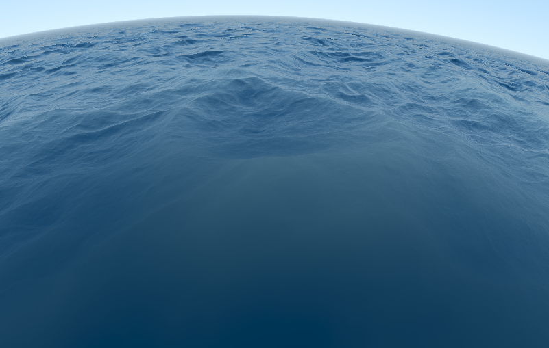
100. An Ocean Shader (Optimized Version)
1 | /* |
ShaderToy
Common Global Variables

Warning
- Avoid writing
iflogic in shaders as much as possible, because it prevents SIMD from running at full efficiency.
Other Terminology
- Homogeneous Coordinates: Representing an n-dimensional vector with an (n+1)-dimensional vector. In 2D, the point (x, y) is represented as (x, y, w) where w is typically 1; if w = 0 it represents a point at infinity. In 3D, the point (x, y, z) is represented as (x, y, z, w). This simplifies graphics calculations and allows points at infinity to be expressed naturally.